A leader line also has a terminator and some text. They are preferably drawn at a 45 angles.

About Leader Objects Autocad Lt 2020 Autodesk Knowledge Network
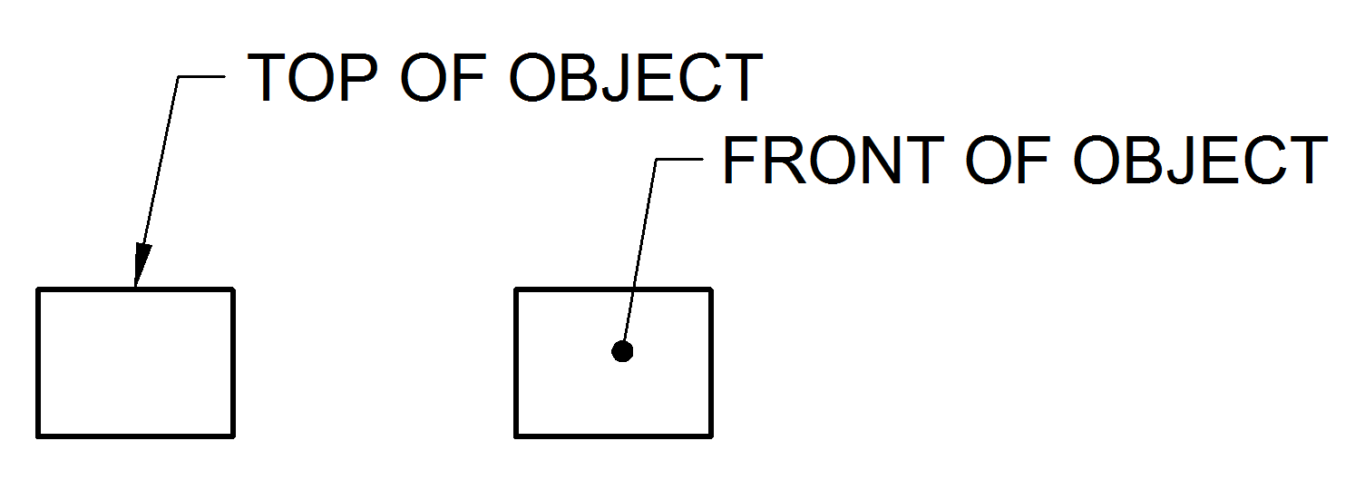
This can be a dot if the line ends within the outline of the part an arrow if the line touches the outline or centre line.

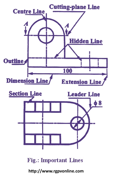
. This line is used to represent the location of a cutting plane. The arrowhead touches the outline while the dot is. This type is also used to draw outlines of adjacent and revolved sections.
Engineering drawing Must include. Leader lines and Termination of the dimension lineThe Language of Lines Basic Blueprint Readinghttpsopenoregonpressbookspubblueprint. A type B line thin continuous straight going from the instruction to the feature.
B Long chain thin line. The person who will read drawings have to learn what they mean. Continuous thin line find its application in engineering drawing as Dimension line Projection line Leader line.
Leader Line Leaders are more thin lines used to point to an area of a drawing requiring a note for explanation. What is a leader line in engineering drawing. A Continuous thick line.
Mechanical Engineering Drawing Mcqs. Leader Line Leaders are more thin lines used to point to an area of a drawing requiring a note for explanation. Visible lines are drawn as solid thick lines.
Engineering drawingDraw the following lines used in projection. A 14To draw the leader line which type of the following line is used. Also Can i add Positional Tolerance without any datum like mentioned in the diagram.
Line conventions in engineering drawing. More specifically the arrow size arrow inclination the text size allow line weight etc should all be the same for all leaders in a drawing. One end of the leader terminates either in an arrowhead or a dot.
A type Continuos Thick. C Continuous thin wavy line. B type Continuous THIN.
The leader line itself should be a continuous Thin line see this post on Linetype Definitions. The person who will read drawings have to learn what they mean. C The leader is drawn vertical or horizontal or curved.
Cutting Plane Line A cutting plane line very heavy helps to show the internal shape at a part or. What are the types of line in drawing. For general engineering drawings the types of lines recommended by the Bureau of Indian Standards shown in table 2 must be used.
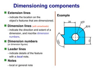
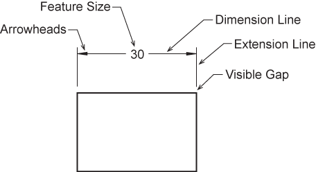
When there is limited space a heavy black. The extension lines for dimensioning should run from the outlines without leaving a gap and extend beyond the dimension lines. Dimension Projection Leader Hatching Lines Dimension Projection Leader Hatching type lines must be drawn thin and continuous.
Uniform leaders can be easily achieved in modern CAD software using annotative. B One end of the leader terminates either in an arrowhead or a dot. Following are the different types of lines used in engineering drawing.
B Long chain thin line. - Answers A leader line is a thin line on a design or blueprint that is used to connect a dimension line with a. Continuous thin line find its application in engineering drawing as Dimension line Projection line Leader line.
Related Questions on Engineering Drawing. This line is used to represent the location of a cutting plane. D Use of common leaders for more than one feature should never be made.
A A leader line is a thin continuous line connecting a note or a dimension figure. B Long chain thin line. Oi Look Here and Read This.
13The primary unit of measurement for engineering drawings and design in the mechanical industries is the. Following are the different types of lines used in engineering drawing. Leader Hatching type lines must be drawn thin and continuous.
All of the above. Last Updated on Sun 13 Mar 2022 Engineering Drawing A leader line is a line referring to some form of feature that could be a dimension an object or an outline. Leader lines and Termination of the dimension line.
A Continuous thick line. 13The primary unit of measurement for engineering drawings and design in the mechanical industries is the. Looking at the drawing.
Where a leader line is used to point towards the feature being dimensioned. A leader line can be drawn curved. All of the above.
A leader line consists of two parts. Leader line is drawn may be 30 or 60 to the bottom of. Technical Drawing Line Types.
Leaders should have a uniform and consistent appearance at all drawings independently of the drawing scale. Continuous thin line find its application in engineering drawing as Dimension line Projection line Leader line. D Use of common leaders for more than one feature should never be made.
Exercise Complete three orthographic views of the object shown on the next slide. A drawing leader consists of an arrow and a text. This line is used to represent the center line for circles and arcs.
This line is located in front of cutting planes outlines of adjacent parts censorial Lines and to state center of gravity. A leader line is a line that establishes a connection between a graphical representation of an item and some text. Related Questions on Engineering Drawing.
A leader line is a line referring to some form of feature that could be a dimension an object or an outline. A common use is to specify the geometry necessary for the construction of a component and is called a detail drawing. You can create leader lines with blocks and notes in 2D panel layouts and harness drawings.
What are the types of line in drawing. For example and also elements in another window ie. Line types are also a language type to communicate between technical peopleEngineering Drawing Intro MCQ With Answers For Online Exam httpswwwtoolsandjobsinfomcqengineering.
C The leader is drawn vertical or horizontal or curved. Continuous thin line find its application in engineering drawing as Dimension line Projection line Leader line. Dimension Marking with Center Lines in Engineering Drawings.
They are preferably drawn at a 45 angles. A 14To draw the leader line which type of the following line is used. C type Continuous THIN FreehandRelated searches for leader line in engineering drawingleader line draftingleader line blueprintline types engineering drawingleader line definitionwhat is a leader linenotes leader line dimensionsdimension leader linesleader lines cadPagination12345NextSee moreEngineering DrawingAn engineering drawing is a type of technical drawing that is used to convey information about an object.
Leader Dimensions- they are usually used to specify a diameter or a radius where a leader line is used to point towards the feature being dimensioned. This line is used to show hidden edges of the main object. Any element that has bounding-box is accepted.
A A leader line is a thin continuous line connecting a note or a dimension figure. For More Engineering Drawing MCQ Click Here. Visible lines represent features that can be seen in the current view.
B One end of the leader terminates either in an arrowhead or a dot. For More Engineering Drawing MCQ Click Here. Mechanical Engineering Drawing Mcqs.
One end of the leader terminates either in an arrowhead or a dot. This is ul li This is This is tableMissing. Leaders should have a uniform and consistent appearance at all drawings independently of the drawing scale.
Technical drawing Lines are used for different purposes to provide specific information for designers manufacturers etc. A leader is a thin line used to connect a dimension with a particular area figure 24. Line types are also a language type to communicate between technical people.
A leader line can be drawn curved. Hi I am new to Engg Drawing and confused if I can Mark Dimension with Center Lines in Engineering Drawings like the attached file. Technical drawing Lines are used for different purposes to provide specific information for designers manufacturers etc.
Also they can be specified using degrees and minutes or degrees minutes and seconds eg 2730or 01540. C type Continuous THIN Freehand. The drawings are linked together by a master drawing or assembly drawing which gives the drawing numbers of the subsequent detailed components quantities required construction materials and possibly 3D images that can be used to locate individual items.
Usually a number of drawings are necessary to completely specify even a simple component. Although mostly consisting of pictographic representations abbreviations and symbols are used for brevity and additional textual explanations may also be provided to convey the necessary informationWikipedia People also search forTechnical DrawingCAD standardsArchitectural DrawingOrthographic ProjectionIsometric ProjectionGeometric Dimensioning and TolerancingPlanSee moreNew content will be added above the current area of focus upon selectionData from. The leader line is drawn from the start element to the end element.
7 Thin chain line find its application as. Hi I am new to Engg Drawing and confused if I can Mark Dimension with Center Lines in Engineering Drawings like the attached file. A leader may also be used to indicate a note or comment about a specific area.
Lines of symmetryA leader line can be drawn curved. WikipediaSuggest an editTrending on Bing Frank Gore one day contractNico Santos Zeke SmithEddie Murphy George Clinton biopicDunkin makeup collectionEstelle Harris SeinfeldTaliban bans poppy productionGerman man forged vaccinationDallas concert shootingSean Manaea tradeAirlines cancel flightsPrince Hamzah titleTiger Woods AugustaSomaliland market fireUN climate report news. Figure 24 - Example drawing with a leader.
Technical Drawing Line Types. Vi Leader Lines A leader or a pointer is a thin continuous line connecting a note or a dimension figure with the feature to which it applies. A type Continuos Thick.
Also Can i add Positional Tolerance without any datum like mentioned in the diagram. Leader line Dash thick line Hidden line Chain thin line Center line. In drawings that do not have cutting planes visible lines will be the thickest lines drawn.
In drawings that do not have cutting planes visible lines will be the thickest lines drawn. 7 Thin chain line find its application as. 7 Thin chain line find its application as.
B type Continuous THIN. A leader points to a bit of our drawing and says. Looking at the drawing.
7 Thin chain line find its application as. C Continuous thin wavy line. To create a leader line on the Draw tab under Annotation click Block leader or.
Extension Lines Drafting Joshua Nava Arts

What Are Lines Types Of Lines In Engineering Drawing Youtube
Leader Lines Toolnotes
Draw The Following Lines Used In Projection I Extension Line Ii Leader Line Iii Construction Line न म नल ख त ल इन क ख च Solutions Ed Question Answer Collection
Engineering Drawing Chapter 07 Dimensioning
Dimension Appearance And Technique

Engineering Drawing Dimensioning Part 1 Youtube

Dimension Guidelines Introduction To Engineering Design Ppt Download
0 comments
Post a Comment